Much more accurate models are available, that use data point curves from actual lithium cell measurements. Some also include SOC / Temp / hysteresis / etc effects. Example here.
But I could not find an open source model that could be modified to represent an LF280 LFP cell or that I trusted. Let me know if someone knows of one ? So, for now a capacitor it is 👍
EVE LF280 example:
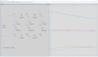
The pink line's slope somewhat tightly follows the 0.1C (28A) and 0.2C (56A) discharge curves, representing a capacitor behavior similar to the cell's at a ~28 to 56A discharge current. That current value was chosen as it is close to our 50A per cell analysis in the previous post, which will also be used in the simulations.
When working within the 3.31V to 3.2V range this capacitor, coupled with a 0.17mΩ series resistor representing the cell's internal resistance, will mimic an LF280 cell's electrical behaviour almost perfectly.
The equivalent capacitance for 280AH of capacity between 3.31V and 3.2V can be calculated via a formula such as Wh = ( VCharged² - VDepleted² ) / ( 7200 / C )
Or it can simply be found, using LTSpice, by setting the capacitor's start voltage at 3.31V, discharging it with a resistor that pulls a 28 to 56A current, and changing the capacitor value until the capacitor's voltage curve hits the 3.2V point after ~5.6 hours of discharge (280 AH / 50A = 5.6H ≈ 20.000 seconds). As shown in the simulation graph above.
Once done, the capacitor model is ready to use, always keeping in mind the specific usage conditions for its validity:
- studying discharge (charge can be done if starting from a charge graph)
- within 3.31V to 3.2V
- studying the linear IV region (not the fully charged or discharged states)
- only up to 60-ish Amps per cell if analyzing the SOC over time (more is fine if studying the dynamic IV response)
Answer: the simulation tweaks show that it takes a ~9.000.000 Farad capacitor ! 😲
With that, we are now ready to do a simple 1S3P simulation to get started and make sure everything is in order before cranking up the complexity on the pack topology and the interconnects.
The excellent 0.15mΩ value is used for the interconnects, per the Making Flexible Busbars post.
Let's start with the same side wiring strategy:
An imbalance issue is immediately apparent:
- Cell #1 starts at 110A, before settling down to 50A after 4 hours once its SOC becomes much lower than the other cells'
- Cell #2 starts at a low 30A current
- Cell #3 starts at a very low 10A current before rising to 50A after 4 hours
Will these cells age at the same rate ? Of course not. Cell #1 is much more stressed and will age faster.
It is not necessarily a deal breaker, though, as it is connected in parallel with the other cells. When its capacity notably degrades, the settling time will simply decrease, as the other cells will start contributing more and earlier.
That's one of the benefits from wiring cells in parallel. Unlike series wiring, a cell with degraded capacity characteristics will still work without disproportionally impacting the battery performance, as long as the others still have life in them.
This said, it will have consequences for the cell monitoring / balancing wire from the BMS. If that wire is connected near Cell #1, the BMS's Cell Under/Overvoltage protection will trip much earlier in case of large charge / discharge currents, than if it is near Cells #2 or #3. We'll come back to that in the final conclusion in How to Improve a non-Star Battery Pack Wiring
But, for now, let's try a few other wiring scenarios.
Midpoint wiring:
- A bit better... cell #1 peaks at a lower 90A, while #2 and #3 start at 30A
- Still a pretty large current imbalance, though
- It takes 3 hours to reach equilibrium
Opposite corners:
- Much better ! Cells #1 & #3 peak at 60A while #2 starts at 30A
- Settling time: 2.5 hours
Great ! And, so far, the sims agree with the conclusions from the simple analysis done in the previous post.
So we can now confidently move on to analyzing in detail the wiring strategy for this van's 4S3P pack. Plot twist: the conclusions above for best topology will not survive for long 😢


Comments
Post a Comment